The factors need to consider once you are doing replacement are:
Ripple current
This is mainly an issue in power supply output stages. Ripples in the supply voltage will cause current through the capacitor, which, in turn, can cause heating.
The heat generated by the ripple current depends on physical characteristics (for example, size and thermal resistance of the package) and the ESR. Both MLCCs and polymers have low ESR and so are far less prone to heating than liquid electrolytics, for example.
The ESR is also stable with temperature so the ripple current limit doesn’t decrease as the temperature rises.
Because MLCCs have very low ESR and generate little heat, the ripple current is often not specified.
Safety
Both MLCC and polymer capacitors are very safe in use. Unlike liquid electrolytics, there is minimal risk of leakage, fire or explosion.
Over-voltage conditions (or reverse bias, for polymer caps) can cause dielectric break down and hence a short circuit, in both types of devices.
Size and packaging
Both MLCC and polymer capacitors are available as surface-mounted devices and have comparable size for a given capacitance value. Polymer caps are available with larger capacitance values and so may be able to replace multiple MLCCs in less space.
Stability
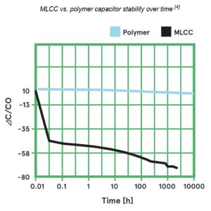
MLCCs show strong capacitance sensitivity to DC bias voltage. This can cause a reduction in capacitance by up to 70%. Polymer caps are much more stable over time, as shown in the diagram to the right. As a result, MLCCs may need to be derated to allow for this decrease. This isn’t the case for polymer devices.
Reliability and lifetime
Because MLCCs are made from brittle materials, there is some vulnerability to thermal or mechanical shock; this is potentially a problem with surface-mounted chip capacitors where circuit board flexing may cause devices to crack and fail.
Polymer caps have a wear-out mechanism where conductivity of the polymer can be degraded by the effects of heat. This is a small effect but may need to be considered for some applications.
Unlike liquid electrolytics, there is no self-healing mechanism so that any damage caused by transient stresses (over-voltage, for example) will be permanent. Hybrid devices, which include a liquid electrolyte as well as the polymer, provide some self-healing capability for damage caused by transient voltages.
The specified lifetime of polymer capacitors can be several years or decades.
Temperature range
Both types have similar operating temperature ranges. However the change in capacitance with temperature for the two types is slightly different.
Polymer caps show a steadily increasing capacitance with temperature while ceramics have greater variation, with a peak at around room temperature and then a fall off at higher temperatures. This is shown in the graph below.
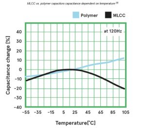
This may need to be taken into account for higher temperature operation.
Price
On a like for like basis, polymer caps may be more expensive, but current MLCC supply shortages are leading to pricing voltatility with regular increases. Additionally, there is an opportunity for cost saving if you can replace multiple MLCCs with a single polymer of the same total capacitance.
There is less need to de-rate polymer capacitors for changes in capacitance over time so this, again, can be a cost saving.
Replacing MLCCs with polymer capacitors: An example application
One of the most common applications where polymers are appropriate for replacing MLCCs is in power supply decoupling. We can consider a simple example of a DC-DC supply which converts the 12 V input to a 1.8 V supply for the electronics, as shown below.
A simple example of a DC-DC power supply
This requires 250 μF on the input and 450 μF on the output. The initial design used MLCCs. These need to be de-rated by 70% for aging and DC bias effects. This means we need a nominal 833 μF on the input and 1500 μF on the output.
These values can be realised with 18 capacitors of 47 μF and 15 of 100 μF.
If we replace these with polymer caps, we can use two 150 μF components on the input and a single 470 uF on the output.
The table below summarises the components used and the saving in size:
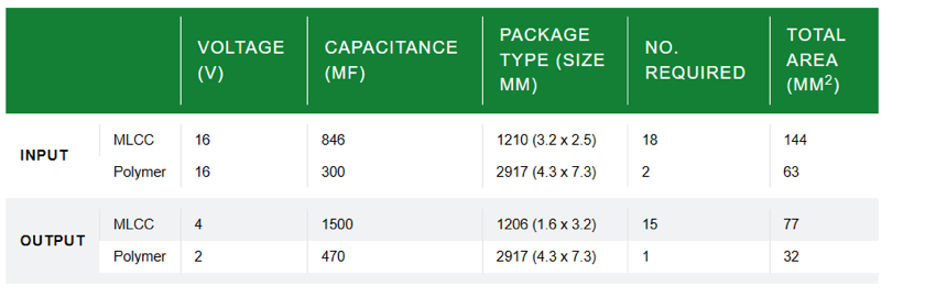
We can see that the area required for the polymer capacitors is less than half that required for MLCCs. There will also be a cost saving of around 30%.
Conclusion
We can see there are many cases where polymer caps can provide a good alternative to MLCC devices, helping to address supply problems.
The key characteristics that may make substitution possible are:
1.Voltage: less than 35V, non-polarised
2.Capacitance: 47uF to 560uF
3.Low ESR / high ripple current
4.Surface-mount package
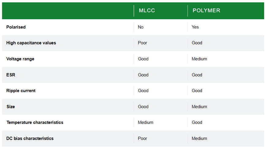
The table below summarises the differences for some of the most important parameters.